





Radar Line up –by Radar chip
Radar Line up –by
Radar chip
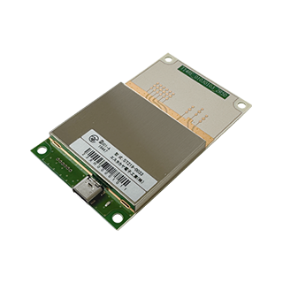
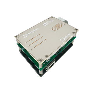
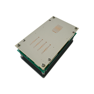
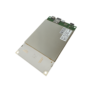
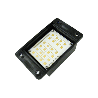

Atlas Series
A model with Analog Devices IC
76GHz/79GHz RAW data output model
Atlas7xG
AT01120112_2D AT01030103_2D AT02010102_3D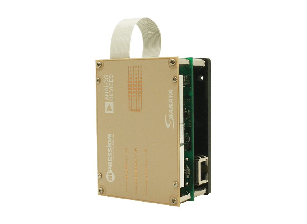

FEATURE
- Better velocity detection performance (high-speed, wideband chirp)
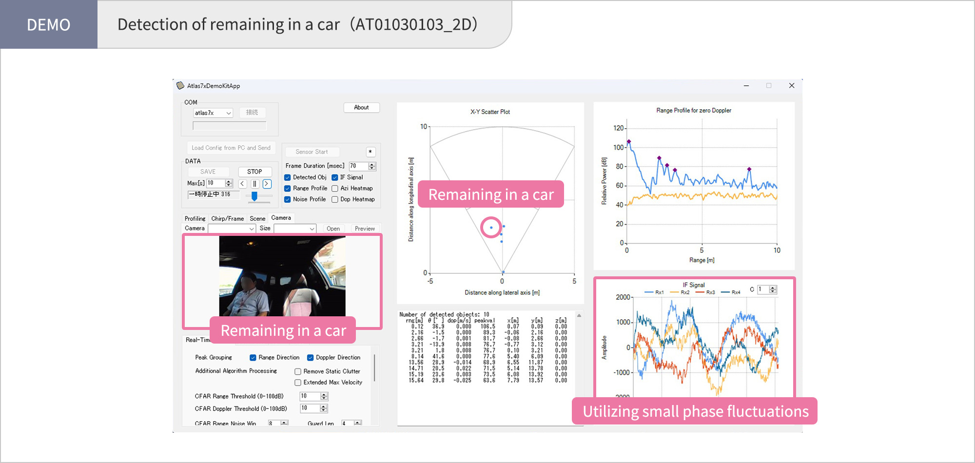
- Suitable for vital sensing applications
- Three antenna configurations available for 2D and 3D detection
- Certified under Japanese radio regulations (Technical Conformity Certification), enabling immediate evaluation
- High range resolution even in long-range (76 GHz) applications (fine distance binning enabled by high-speed ADC)
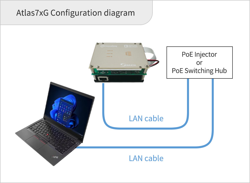
- PoE+ supported, requiring only a single LAN cable (no separate power cable needed)
- Raw Data output available
- Includes evaluation software (Connects Windows PC via USB cable)
Common Specifications
| Items | Unit | Performance | |
|---|---|---|---|
| 76 GHz Model | 79 GHz Model | ||
| Module Size | mm | 65(W) × 44(D) × 93(H) | |
| Interfaces | Ethernet 1000BASE-T PoE+ | ||
| Power Consumption (Avg) | W | 4.3 | |
| Occupied Bandwidth | GHz | 76.4 - 76.75 | 77.3 - 80.9 |
| Maximum Detection Range | m | 117 | 33 |
| Angular Measurement Range | deg | ±45 | |
| Range Resolution | cm | 86 | 13 |
| Maximum Detectable Velocity | km/h | 55 | 27 |
| Chirp Duration | us | 21.25 | 42.5 |
| Operating Temperature Range | ℃ | -20 ~ +55 | |
| Data Format | rawdata | ||
Module Specifications
| Module Name | AT01120112_2D | AT01030103_2D | AT02010102_3D | |
|---|---|---|---|---|
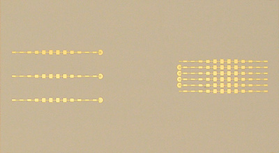
| Antenna Type |
|

|

|
|
| Transmit (Tx) | Patch | 12 | 3 | 2 |
| Receive (Rx) | Patch | 12 | 3 | 2 |
| Transmit Antenna Half-Power Beamwidth (Typ) | ||||
| Azimuth | deg | 66 | 68 | 37 |
| Elevation | deg | 8 | 26 | 75 |
| Receive Antenna Half-Power Beamwidth (Typ) | ||||
| Azimuth | deg | 99 | 66 | 74 |
| Elevation | deg | 9 | 26 | 49 |
| Operating Frequency | GHz | 76 | 79 | 79 |
| Polarization | Vertical | Vertical | Vertical | |
| 3D Detection | Not Supported | Not Supported | Supported | |
| Output Power (Typ) | dBm EIRP | 21 | 17 | 15 |
Contents
- ・Atlas7xG Radar Module
- ・Software, USB drivers and user manual (Available for download from our website)
DOCUMENT REQUEST
*Please contact our agents and distributors for inquiries about the evaluation kit.
Click here to purchase24GHz RAW data output model
Atlas24
AT1_01080108V AT2_01040104V AT3_01020102V AT4_01080108HAT5_01040104H AT6_01020102H
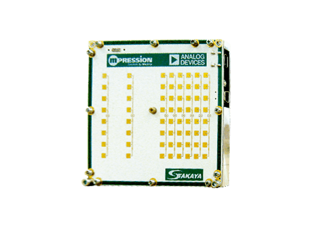
FEATURE
- The only MIMO model in the 24 GHz band
- Raw Data output available
- Certified under Japanese radio regulations (Technical Conformity Certification), enabling immediate evaluation
- Long-range detection (maximum detection range: 240 m)
- Six antenna pattern variations with different radiation angles and polarizations
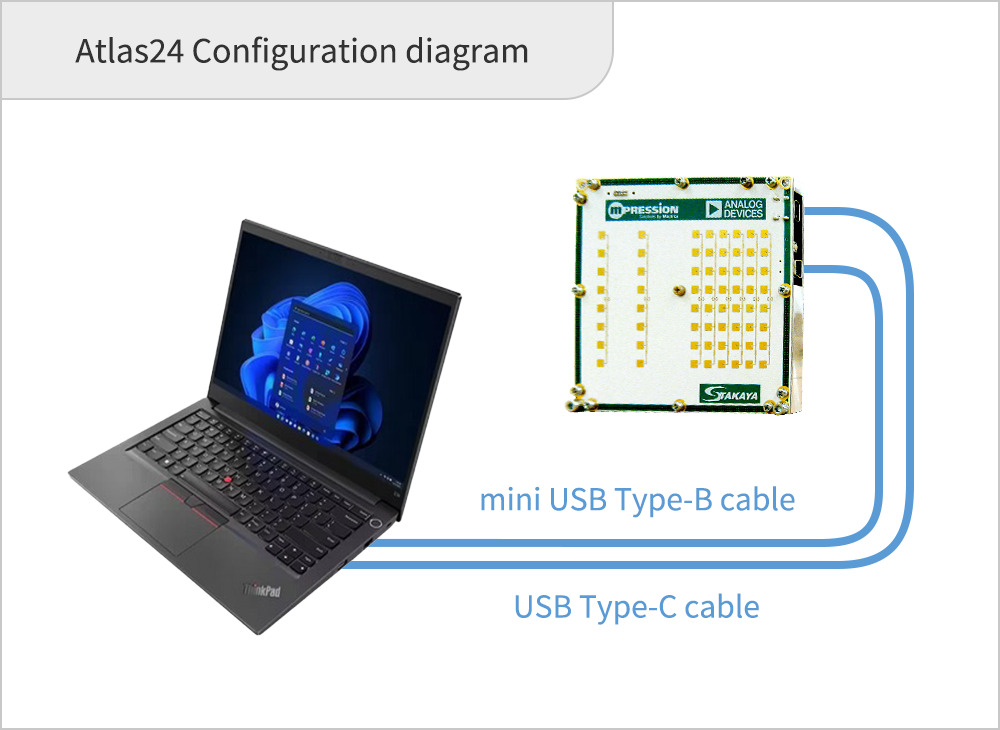
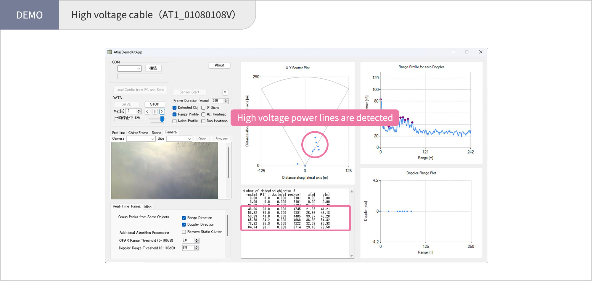
- Includes evaluation software (Connects Windows PC via USB cable)
Common Specifications
| Item | Unit | Function Performance |
|---|---|---|
| Module Size | mm | 100(W) × 100(D) × 7.5(H) |
| Interface | USB2.0(DATA) USB3.0(bus power) | |
| Power Supply Voltage | V | 5.0 |
| Current Consumption | A | 0.7 |
| Operating Frequency | GHz | 24.05 ~ 24.25 |
| Modulation Bandwidth | MHz | 180、80 ※1 |
| Measurement Range (Typ) | m |
0.75 ~ 107 2.3 ~ 241 ※1 |
| Angular Measurement Range (Typ) | deg | ±40 |
| Chirp Duration | us | 260 |
Module Specifications
| Module Model Name | AT1_01080108V | AT2_01040104V | AT3_01020102V | AT4_01080108H | AT5_01040104H | AT6_01020102H | |
|---|---|---|---|---|---|---|---|
| Antenna Type |
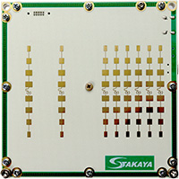
|
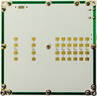
|
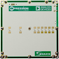
|
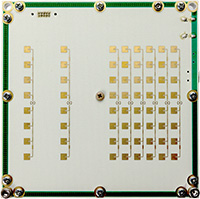
|
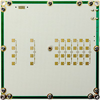
|
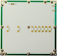
|
|
| Transmit (Tx) | Patch | 1×8 | 1×4 | 1×2 | 1×8 | 1×4 | 1×2 |
| Receive (Rx) | Patch | 1×8 | 1×4 | 1×2 | 1×8 | 1×4 | 1×2 |
| Transmit Antenna Half-Power Beamwidth (Typ) | |||||||
| Azimuth | deg | ±40 | ±40 | ±40 | ±70 | ±70 | ±70 |
| Elevation | deg | ±7 | ±10 | ±20 | ±7 | ±10 | ±20 |
| Receive Antenna Half-Power Beamwidth (Typ) | |||||||
| Azimuth | deg | ±40 | ±40 | ±40 | ±70 | ±70 | ±70 |
| Elevation | deg | ±7 | ±10 | ±20 | ±7 | ±10 | ±20 |
| Polarization | Vertical | Vertical | Vertical | Horizontal | Horizontal | Horizontal | |
| Output Power(Typ) | dBm EIRP | 20 | 18.5 | 16 | 18.5 | 15 | 12 |
Contents
- ・Atlas24 Radar Module
- ・Tripod Mount Adapter
- ・USB 2.0 Cable (A-Mini B)
- ・Software, USB drivers and user manual (Available for download from our website)
DOCUMENT REQUEST
*Please contact our agents and distributors for inquiries about the evaluation kit.
Click here to purchase28/39GHz mmwave phased array antenna Module
Dragonfly
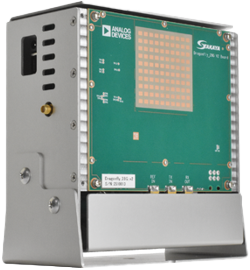
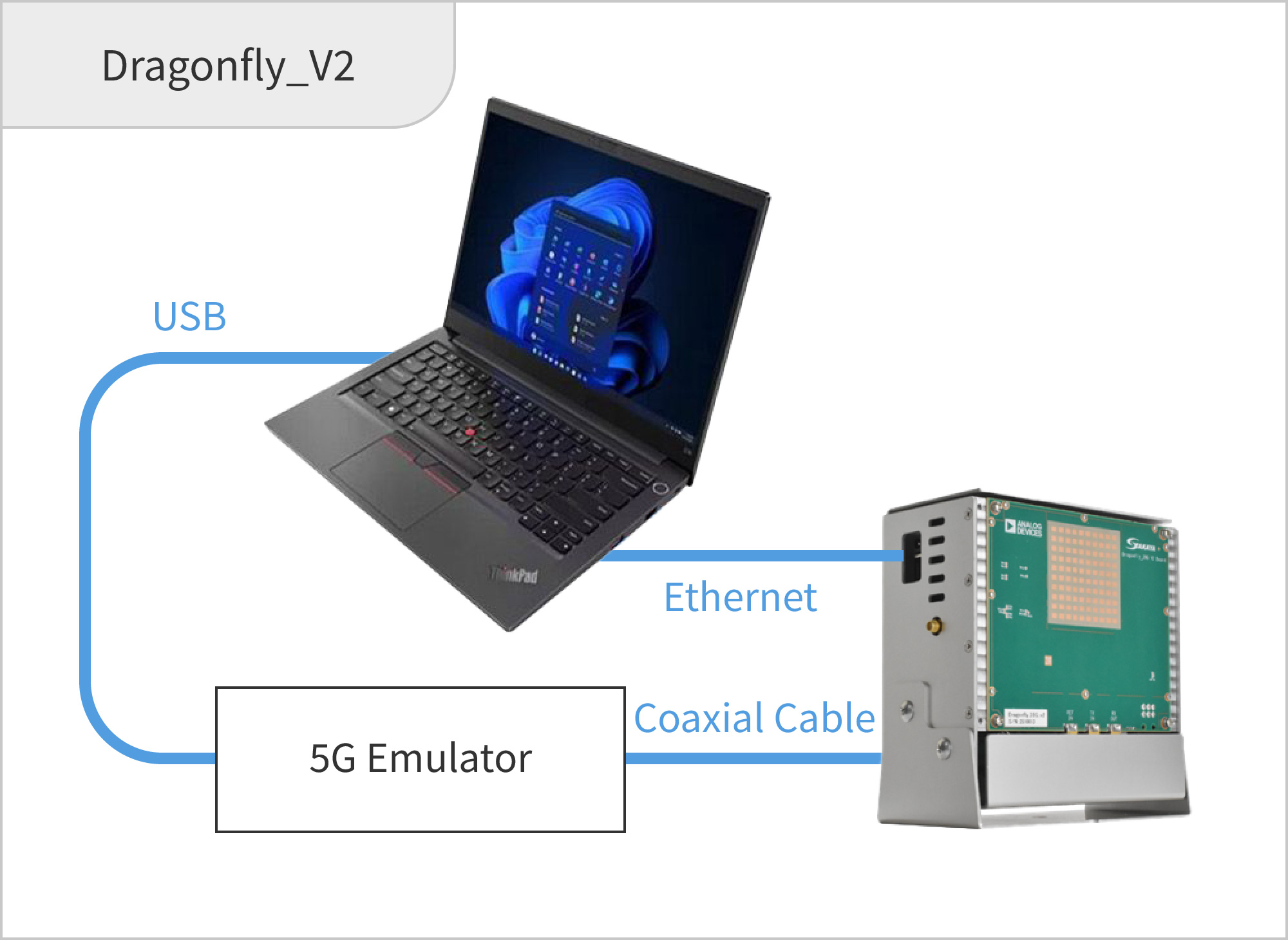
![[DEMO] ISAC Demonstration](https://www.s-takaya.co.jp/wp-content/themes/s-takaya/assets/img/product/evaluation_kit/dragonfly_v2_img02_en.jpg)
FEATURE
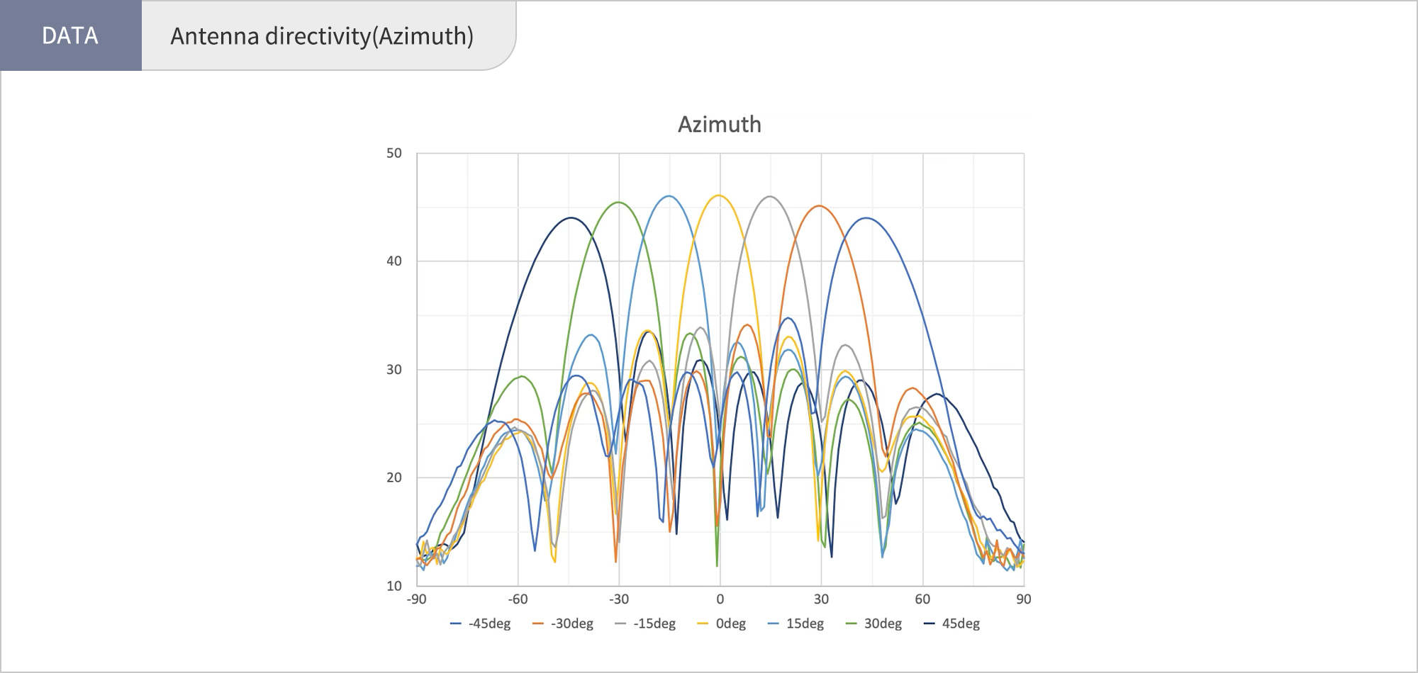
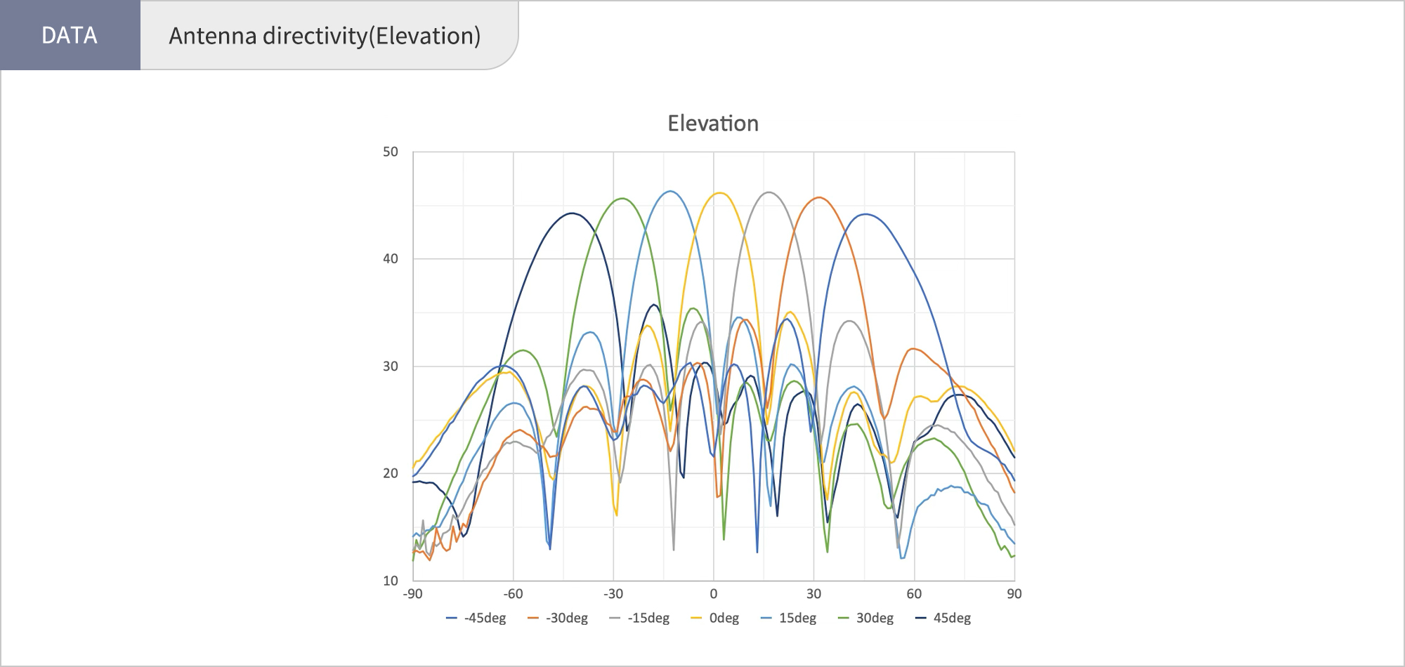
- You can evaluateBeam steering using actual RF signals via antennas.
- You can evaluateBeamforming and beam steering at the system level.
- Enables the creation of a system-wide verification environment for FR2 5G systems. (Dragonfly is used as a phased array antenna module.)
- Research and development of 6G and ISAC (Integrated Sensing and Communication)
- Custom development
- A system development kit (SDK) has also been developed, enabling beam steering via PC.
- Reference code is available for PC control using MATLAB.
Module Specifications
| Item | Performance | |
|---|---|---|
| Phased Array Antenna Module Appearance | 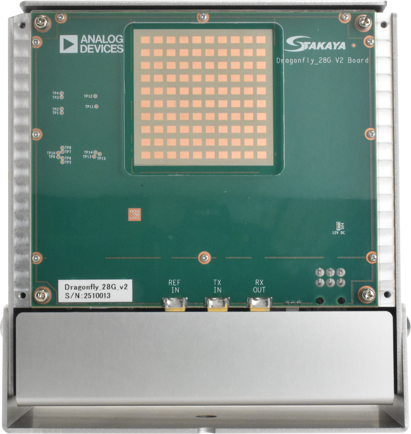 |
|
| Number of Antenna Elements | 64 (8×8) | |
| Module Size | mm | 158(W)×88(D)×174(H) |
| Interface | Ethernet 1000Base-T (UDC) | |
| Power Consumption (Max.) | W | 36 |
| Operating Temperature Range | ℃ | -20~85 |
| Polarization | Vertical | |
| Frequency Band | GHz | 27.8-29.1GHz |
| Duplex Communication Method | TDD | |
| Output Power (Peak) | dBm EIRP | 46 |
| Beam Steering Angle | degrees | ±45 |
| Beam Steering Angle Step | degrees | 2 |
| Receiver Gain | dB | 30 |
| Reference Clock | MHz | 122.88 |
| IF Frequency | GHz | 3.5 |
| IF Bandwidth | MHz | ±200 |
| Maximum Input Power (TX) | dBm | -10 |
| Maximum Input Power (RX) | dBm EIRP | -30 |
Contents
- ・Dragonfly_V2 Module
- ・Two AC Adapters (for Dragonfly and ZYBO)
- ・Ethernet Cable (10 m)
- ・Software, USB drivers and user manual (Available for download from our website)
Optional Accessories
- ・Ethernet Hub
- ・Coaxial Cable with SMA Plug
- ・ADI Pluto (Software-Defined Radio Active Learning Module)
DOCUMENT REQUEST
*Please contact our agents and distributors for inquiries about the evaluation kit.
Click here for introductionby Analog devices. Click here to purchase
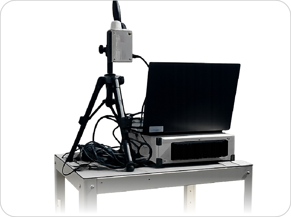
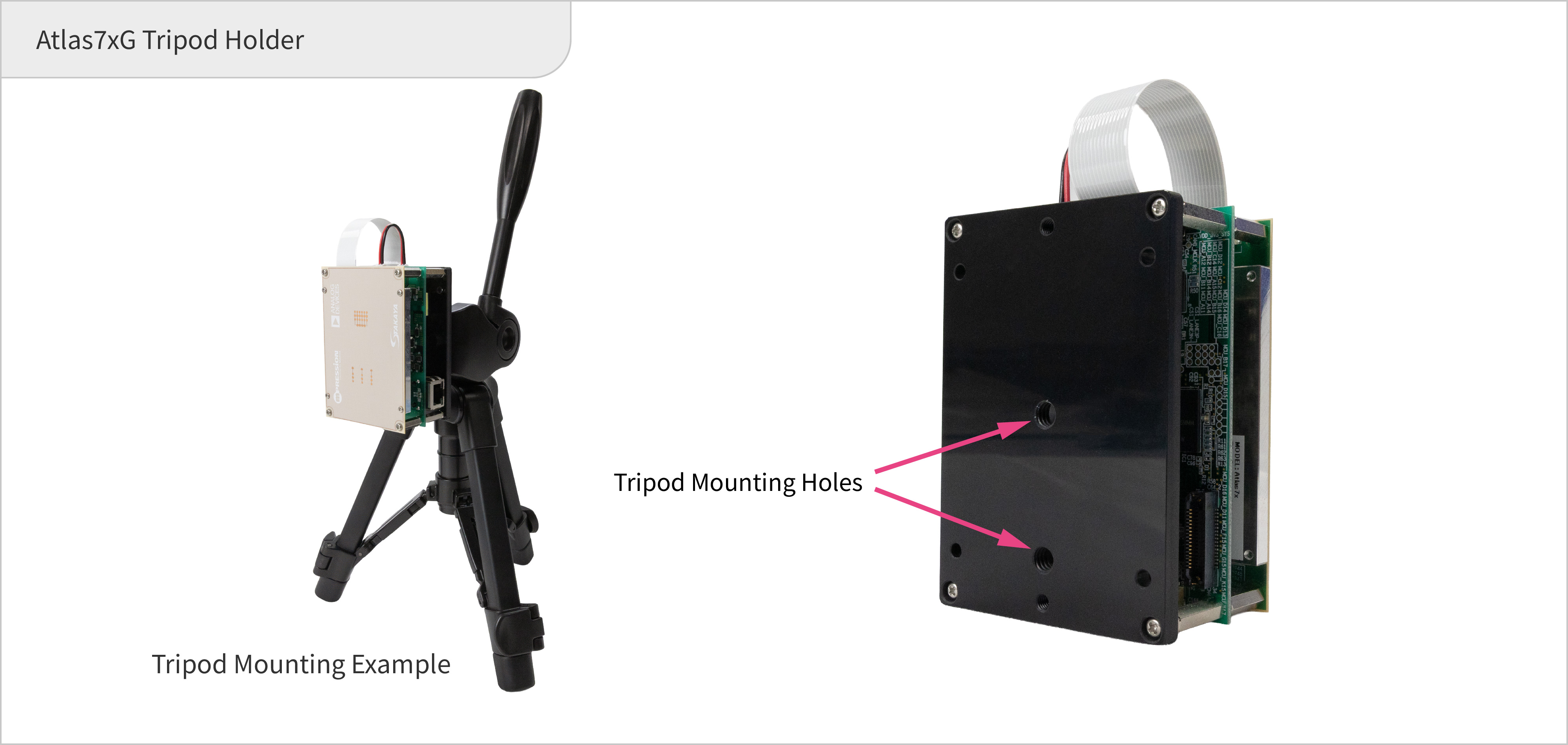
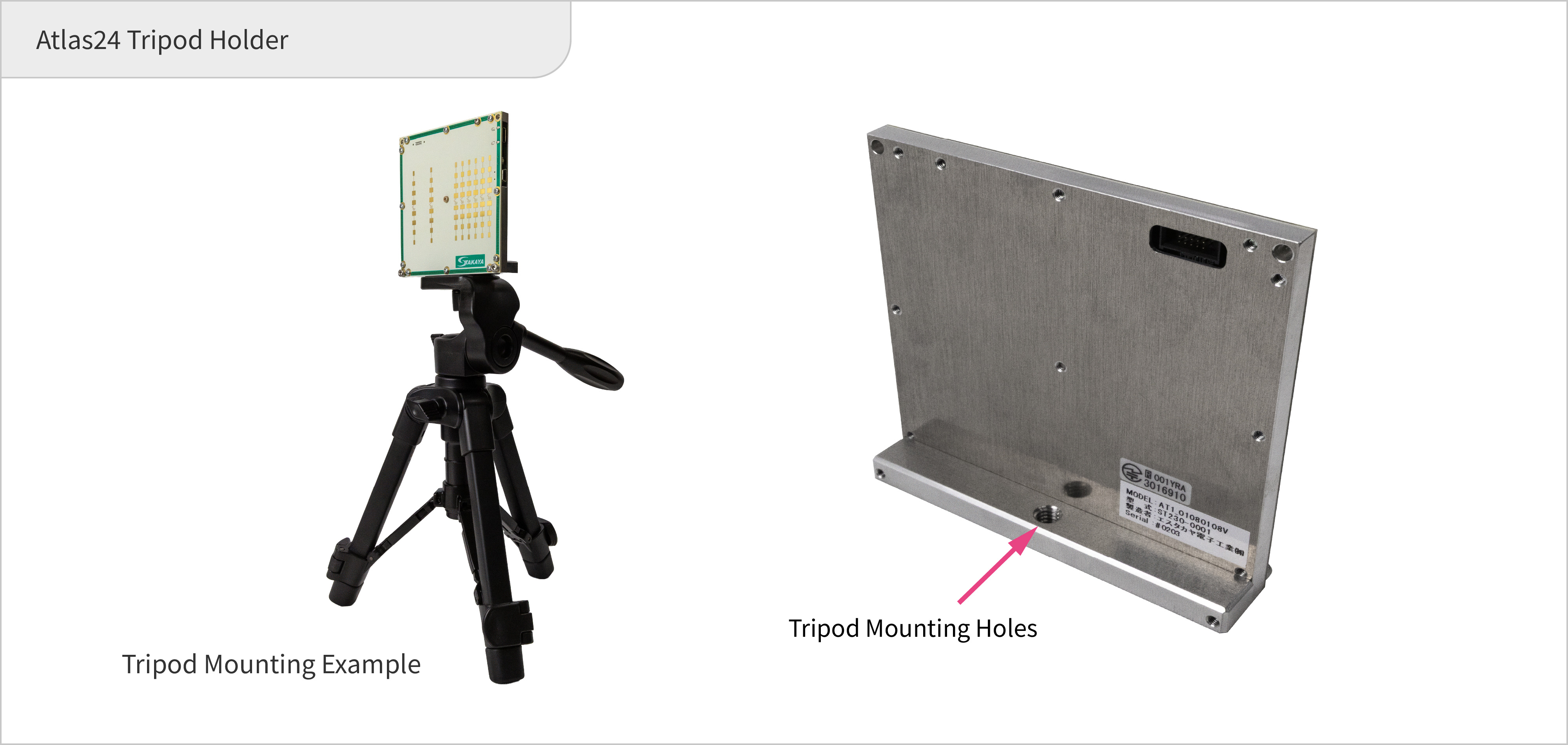
Tripod holder (included with all models of Atlas series)
A tripod mounting fixture is included, so evaluations can be performed by mounting the device to a standard/normal tripod.
DOCUMENT REQUEST
DOCUMENT REQUEST
Distributor of Atlas series

|
MACNICA, Inc. ALTIMA Company | contact |
|---|